Electric Drive Train Simulator.
Introduction
Electric Drive Train Simulator (EDTSim) is an easy to use drive train development tool that allows you to select the motor, battery, wheel size, gear ratio and mass of an electric drive train and then predicts the performance of that combination of components. You can view the predictions numerically and there is also a test drive mode so you can take it for a test drive and really get a feel of what it would be like to drive.
While all data and equations used in EDTSim are believed to be accurate, no computer simulation can be 100% accurate, there are virtually an unlimited number of variables that can affect a real system, and all information provided by EDTSim should be used with this in mind.
Working with high-power motors and batteries can be dangerous and should not be attempted without proper experience or supervision.
System requirements:
EDTSim requires a PC with 350 MHz or faster
Intel or AMD processor. A hardware accelerated graphics card. Windows 95, 98,
ME, 2000 or XP operating system and DirectX 6.1 or higher and 30MB free hard
disk space. A joystick is recommended.
Installation
Double-click “setup.exe” and follow the instructions. To un-install go to the Windows start menu and select “EDTSim” then “un-install”.
The main build window
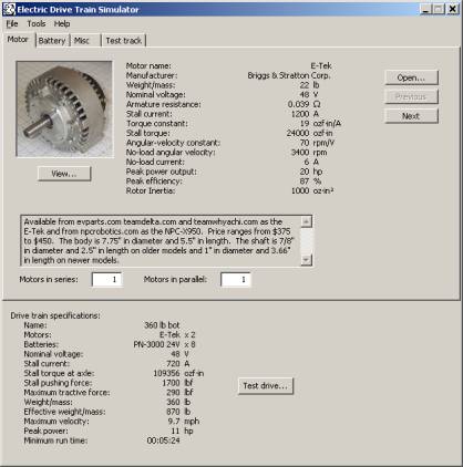
This is the main build window. It contains the File, Tools and Help menus. It also contains a series of tabs where you can choose the various components and settings. A summary of the system specifications is shown at the bottom of the window.
Drive train specifications: This is a summary of all combined components.
Name: Drive train name as set under the Misc tab.
Motors: This is the name and number of motors selected.
Batteries: This is the name and number of motors selected.
Nominal voltage: This is the nominal (average) voltage of the batteries selected.
Stall current: This is the drive train’s stall current based on resistance of all motors, batteries and additional resistance selected.
Stall torque: This is the stall torque generated at the axle if the axle is prevented from turning.
Stall pushing force: This is the pushing force generated at the wheel surface. In practice this amount of force will never be generated, because the wheels will begin to slip with less force (see “Maximum tractive force”). The most pushing force the wheels can generate is the weight of the drive train multiplied by the wheel/surface coefficient of friction.
Maximum tractive force: This is maximum force the tires can exert on the ground to push the drive train forward. It is based on the weight over the drive wheels multiplied by the wheel/surface coefficient of friction.
Weight/mass: This is the total translational weight/mass of the drive train.
Effective weight/mass: An often-neglected aspect of vehicle acceleration is the rotational inertia of the vehicles rotating parts. This number represents the translational inertia of the drive train added to the rotational inertia of all the rotating parts of the drive train.
Maximum velocity: This is the maximum speed the drive train can reach on a level surface.
Peak power: This is the maximum power all of the drive trains combined components can generate.
Minimum run time: This is a very rough estimate of the minimum time the drive train will run before the batteries reach the 100% discharge. Driving style and drive train type can drastically affect the run time. The estimate is based on the assumption that the maximum tractive force determines the maximum current draw of the drive train. The estimate will give you a run time similar to driving into the wall until the battery is discharged.
Test drive: This button runs the test drive simulation.
The motor tab
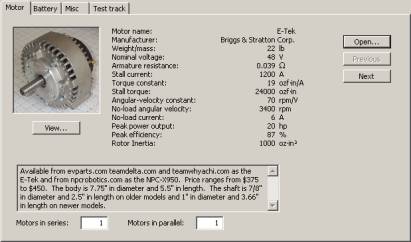
This is where you select the motor for your drive train. You can use the “Open…” button to choose the motor file you want to open or you can use the “Previous” and “Next” buttons to step through all the motor files. The “View…” button will show a larger picture of the motor.
Name: This is the common name or part number of the motor.
Manufacturer: This is the company that manufactured the motor.
Weight/mass: This is the weight or mass of the motor.
Nominal voltage: This is the voltage the motor was designed to run at.
Armature resistance: This is the electrical resistance of the motor’s windings.
Stall current: This is the amount of current that will pass through the motor when the nominal voltage is applied to the to it.
Torque constant: This is the amount of torque generated for each amp of current passing through the motor.
Stall torque: This is the amount of torque generated while the motor is stalled at the nominal voltage.
Angular-velocity constant: This is one of the motor constants, it is the speed at which the motor will turn for each Volt applied to the motor.
No-load angular velocity: This is the speed at which the motor will turn with no load attached at the nominal voltage.
No-load current: This is the amount of current passing through the motor when no load is attached to the motor and it is spinning at the “No-load angular velocity”.
Peak Power: This is the maximum amount of output power the motor will generate. Peak power usually occurs at 50% of the stall current and 50% of the no-load angular velocity.
Peak efficiency: This the maximum percentage of output power that can be generated from input power.
Rotor Inertia: This is rotational inertia of the motor’s armature.
Notes: This window contains miscellaneous information about the motor such as size and where the motor can be purchased.
Motors in series: This allows you to set the number of motors connected in series. The simulation assumes all motors have their shafts mechanically connected.
Motors in parallel: This allows you to set the number of motors connected in parallel. The simulation assumes all motors have their shafts mechanically connected.
The battery tab
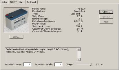
This is where you select the batteries for your drive train. You can use the “Open…” button to choose the battery file you want to open or you can use the “Previous” and “Next” buttons to step through all the motor files. The “View…” button will show a larger picture of the battery.
Name: This is the common name or part number of the battery.
Manufacturer: This is the company that manufactured the battery.
Type: This is the type of battery chemistry.
Weight/mass: This is the weight or mass of the battery.
Nominal voltage: This is the average voltage of the voltage of the battery. A fully charged battery will have a slightly higher voltage and discharged will have a lower voltage.
Fully charged resistance: This is the batteries internal resistance when fully charged.
Peukert value: A battery’s capacity will vary depending on the discharge current. This number is used to calculate the battery’s capacity at different discharge currents.
Capacity at C/x discharge rate: This is the batteries capacity in Amp-hours (Ah) at the x discharge time. The desired discharge time x can be set in the “File->Options” menu.
Current at C/x discharge rate: This is how much current the battery can generate for the x discharge time.
Short circuit current: This is the maximum current the battery can source.
Notes: This window contains miscellaneous information about the battery such as size and where the motor can be purchased.
Batteries in series: This allows you to set the number of batteries connected in series. When connecting batteries together in series their voltages are added together and the capacity remains the same.
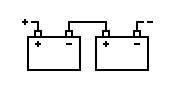
Batteries in parallel: This allows you to set the number of batteries connected in parallel. When connecting batteries together in parallel their capacities are added together and the voltage remains the same.
Charge: This slider sets the battery’s state of charge. A battery’s voltage drops and it’s resistance increases as the battery discharges. Moving this slider allows you to see how a drive train’s performance will change as the battery discharges.
The Misc tab
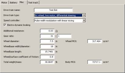
This is where you set various miscellaneous values used in the drive
train.
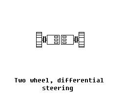
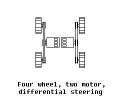
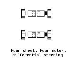
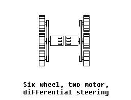
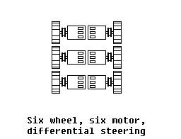
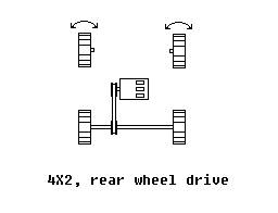
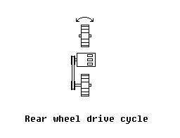
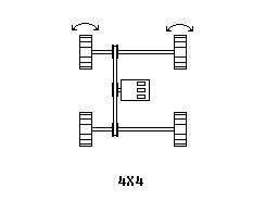
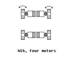
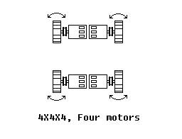
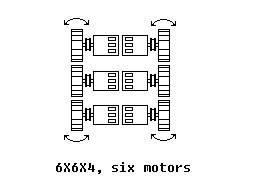
Drive train type: This is the type of drive train to simulate.
|
|
|
|
|
|
|
|
|
|
|
|
|
|
|
|
|
|

Speed controller type: This is the type of speed controller. The choices are pulse width modulation (PWM), which is a variable speed type of controller and binary, which is similar to a relay-based controller that only has on and off.
Electro-dynamic braking: This check box enables electro-dynamic braking which means the motors terminals are shorted together when the speed controller is in the off position. This generates a braking force that will cause the drive train to stop more quickly.
Gear ratio: This is the motor speed to axle speed gear ratio.
Wheel diameter: This is to set the diameter of the wheels. While the simulation will behave if the wheels were this size the wheels on the avatar used in the simulation will not change size.
Wheel and gearbox MOI: This is the combined “Moment of Inertia” of the wheel and gearbox. See appendix A for some estimates of wheel MOI and some formulas for calculating MOI.
Wheelbase width: This is the distance between wheel centers. While the simulation will behave as if the wheels were this distance apart the wheelbase distance on the avatar used in the simulation will not change.
Wheelbase length: This is the front to back distance between the wheel centers.
Wheel/surface coefficient of friction: This is used to set the coefficient of friction between the wheel surface and driving surface. 0.8 is a reasonable value for rubber wheels on an asphalt surface. If all of the weight of the drive train is not resting on the two drive wheels, this value can be reduced to reflect that.
Total weight/mass: This is the total weight/mass of the drive train.
Body MOI: This is the MOI of the drive train. See appendix A for some formulas for calculating MOI.
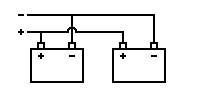
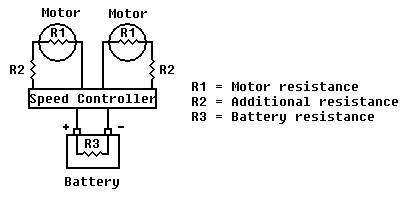
Additional resistance: The resistance of the motors and batteries is automatically calculated. Any additional resistance of the speed controller and wiring can be entered here. This value is per channel. A schematic of the computer model is shown below.
The Test track tab
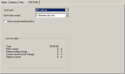
Test track: This is test track that will be used in the test drive simulation.
Drive train avatar: This is used to select the 3D model that will be displayed in the test simulation.
Show actual wheel positions: Normally the wheels are shown at a position that looks natural with the drive train body, checking this box will display the wheels according to the drive train length and width settings. The physics simulator always uses the drive train length and width settings when calculating forces regardless of this setting.
Last run data: This box contains information from the last test drive simulation that might be useful in selecting components for your drive train.
Time: This is the amount of time the test drive simulation ran.
RMS current: RMS current is defined as the effective continuous current of a signal of varying current. This can be useful for sizing a speed controller. You should choose a speed controller with a continuous current rating higher than the RMS current. Remember to divide the RMS current by two to get the RMS current per channel, which is how most multi channel speed controllers are rated. This should be used carefully, because it is possible exceed a speed controllers maximum current while not exceeding its continuous current.
Battery ending charge: This is percentage of charge remaining in the battery when the test drive simulation ended.
Lowest closed circuit Voltage: This is the lowest voltage measured across the batteries terminals while a load is connected. This is important, because some speed controllers will shut down if the voltage drops below a certain level.
Highest current: This is the highest current measured during the test drive simulation.
Test drive display
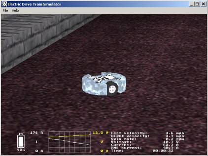
Battery picture: The picture of the battery represents the current level of battery charge. Note: the percentage display can go below 0%. 0% is the point at which the battery manufacturer recommends you stop discharging the battery. You can discharge the battery further, but you will be shortening the battery’s life.
Graph: The white line is a graph of the
instantaneous current, and the yellow is the instantaneous Voltage.
Left velocity: This is the speed that the surface of the left side wheel is spinning at. If this display is yellow, it means the wheel is slipping.
Right velocity: This is the speed that the surface of the right side wheel is spinning at. If this display is yellow, it means the wheel is slipping.
Spin rate: This is the rate at which the drive train is turning.
Voltage: This is the instantaneous voltage.
Current: This is the instantaneous current.
RMS current: the rate See the description under “test track tab” for more details.
Time: This is time the test drive simulation has been running.
Motor editor
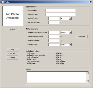
The motor editor allows you to create new motors from manufacturer data or test data and make changes to existing motors.
Open BMP… This allows you to add a picture to the motor’s description. It must be a Windows BMP format picture. It is best if the picture has a square aspect ratio.
Open… This loads an existing motor into the motor editor.
Save as… This saves your newly created or edited motor.
Cancel This will exit the motor editor. You will lose any motor data that was not saved.
Motor name: Enter a name for the motor here.
Manufacturer: Enter the motor’s manufacturer here.
Motor constants: You can enter the motor constants if you know them here. If you have test data press the “Test data…” button to enter your test data and the motor editor will calculate the motor constants from that.
Angular-velocity constant: Enter the motor’s angular velocity constant here.
Armature resistance: Enter the motor’s armature resistance here.
No-load current: Enter the motor’s no-load current here.
Rotor Inertia: This is rotational inertia of the motor’s armature. See appendix A for some MOI calculations.
Calculated Values: These are the motor’s power, velocity, efficiency, stall current and stall torque specifications based on the entered motor constants and nominal voltage when connected to a regulated power supply.
Notes: Enter any other text to describe the motor here. This field is limited to 512 characters.
Motor test data
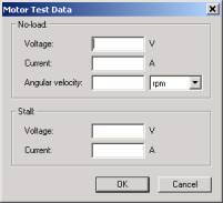
This window is used to calculate the motor constants from test data.
Voltage: Enter the voltage measured across the motor terminals while it is running with no load attached.
Current: Enter the current measured while the motor is running with no load attached. This test is best done as close to the motor’s nominal voltage as possible since the current will vary with voltage.
Angular velocity: Enter the motor’s speed while running with no load attached here.
Stall Voltage: Enter the voltage measured across the motor’s terminals when it is stalled. This test can be dangerous. While stalled a motor can heat up quickly and if the motor’s shaft is not properly locked it can break loose and cause injury. It is not necessary to stall the motor at full voltage. Choosing a lower voltage that creates at least 10 amps of current is sufficient to test a large motor. The current will also vary depending on the position of the armature and should be tested in several positions with the average voltage used.
Stall current: Enter the current measured while the motor is stalled. This test can be dangerous. While stalled a motor can heat up quickly and if the motor’s shaft is not properly locked it can break loose and cause injury. It is not necessary to stall the motor at full voltage. Choosing a lower voltage that creates at least 10 amps of current is sufficient to test a large motor. The current will also vary depending on the position of the armature and should be tested in several positions with the average current used.
Battery editor
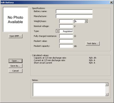
The battery editor allows you to create new batteries from manufacturer data or test data and make changes to existing batteries.
Open BMP… This allows you to add a picture to the battery’s description. It must be a Windows BMP format picture. It is best if the picture has a square aspect ratio.
Open… This loads an existing battery into the battery editor.
Save as… This saves your newly created or edited battery.
Cancel This will exit the battery editor. You will lose any battery information that was not saved.
Name: Enter a name for the battery here.
Manufacturer: Enter the battery’s manufacturer here.
Weight/mass: Enter the weight/mass of the battery here.
Nominal voltage: Enter the battery’s nominal (average) voltage here.
Type: Enter the battery’s chemistry type here. “Regulated” is used for power sources that don’t have a varying voltage, like a regulated power supply.
Fully charged resistance: Enter the battery’s fully charged electrical resistance here. This is difficult to measure, but it is usually listed on data sheets from the battery manufacturers. A battery’s resistance will vary with the state of charge, which is handled in the test drive simulator.
Peukert value and Peukert capacity: These values are not usually provided by manufacturers, but these values can be calculated from two different capacities at two different discharge currents. Press the “Test data…” button and enter them.
Short circuit current: This is the maximum current the battery can source.
Notes: Enter any other text to describe the battery here. This field is limited to 512 characters.
Battery test data
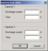
Capacity 1 Discharge current: When a battery is tested for capacity it is discharged at a constant current until it is discharged. The amount of discharge current is entered here.
Capacity 1 Discharge time: The time it took to discharge at the above current is entered here.
Capacity 2: These are the same values as above, but should be results from a different discharge rate
Options
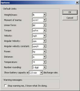
Default units: Use the list boxes to set the type of units you see the motor, battery and drive train data in.
Number rounding: Set the number of significant digits to be displayed.
Show battery capacity a C/X discharge rate: A battery’s capacity will vary with how quickly it is discharged. Use this box to set your estimated discharge time.
Appendix A: Calculating MOI.
Inertia is the property of matter, which resists acceleration. MOI, moment of inertia, or rotational inertia is the property of matter, which resists rotational acceleration.
MOI of disk = (1/2) * mass * radius² = (1/8) * mass * diameter²
MOI of rectangle = (1/12) * mass * (length² + width²)
Here are some estimated MOI values for some popular wheels:
|
Wheel |
MOI |
|
1 5/8” caster |
0.2570
oz·in² |
|
2” caster |
0.5324
oz·in² |
|
2 1/2” caster |
1.758
oz·in² |
|
3” caster |
2.812
oz·in² |
|
3 1/2” caster |
7.102 oz·in² |
|
4” caster |
8.100
oz·in² |
|
5” caster |
19.84
oz·in² |
|
6” caster |
67.28
oz·in² |
|
8” caster |
264.8
oz·in² |
|
12” caster |
2008
oz·in² |
|
8” Foam filled tire and
wheel |
332.8
oz·in² |
|
10” Foam filled tire and
wheel |
1000
oz·in² |
|
12” Foam filled tire and
wheel |
2540
oz·in² |
|
14” Foam filled tire and
wheel |
4498
oz·in² |
Here are some estimated body MOI values for a disk shaped body style:
|
|
Weight/mass |
||||||
|
Diameter |
1 lb |
12 lb |
30 lb |
60 lb |
120 lb |
220 lb |
340 lb |
|
6” |
72 oz·in² |
864 oz·in² |
2160 oz·in² |
4320 oz·in² |
8640 oz·in² |
15840 oz·in² |
24480 oz·in² |
|
1’ |
288 oz·in² |
3456 oz·in² |
5760 oz·in² |
17280 oz·in² |
34560 oz·in² |
63360 oz·in² |
97920 oz·in² |
|
1.5’ |
648 oz·in² |
7776 oz·in² |
19440 oz·in² |
38880 oz·in² |
77760 oz·in² |
71380 oz·in² |
220320 oz·in² |
|
2’ |
1152 oz·in² |
13824 oz·in² |
34560 oz·in² |
69120 oz·in² |
138240 oz·in² |
253440 oz·in² |
391680 oz·in² |
|
2.5’ |
1800 oz·in² |
21600 oz·in² |
54000 oz·in² |
108000 oz·in² |
216000 oz·in² |
396000 oz·in² |
612000 oz·in² |
|
3’ |
2592 oz·in² |
31104 oz·in² |
77760 oz·in² |
155520 oz·in² |
311040 oz·in² |
570240 oz·in² |
881280 oz·in² |
|
3.5’ |
3528 oz·in² |
42336 oz·in² |
105849 oz·in² |
211680 oz·in² |
423360 oz·in² |
776160 oz·in² |
1199520 oz·in² |
|
4’ |
4608 oz·in² |
55296 oz·in² |
138240 oz·in² |
276480 oz·in² |
552960 oz·in² |
1013760 oz·in² |
1566720 oz·in² |